The Battery Cycle #7: Stress level: what hurts?
This is a contribution from Claudius Jehle, CEO of volytica diagnostics GmbH. It’s the seventh of a series of knowledge articles on topics around Li-Ion Batteries, written by Claudius and other field-related experts.
What does actually hurt a battery? What influences the rate of degradation and which measures can be taken to decrease the progression of capacity fade?
Battery degradation: how to minimize it? Influencing factors
The short answer is: there are only a few universal rules. Generally speaking, each battery cell type has their unique susceptibilities to usage and external influences. Some cell types are tailored to withstand low temperatures, others high currents etc., and as most often in life there is no such thing as a free lunch. An optimization in one aspect comes at a price in another region – more on that later.
First of all, let’s introduce the concepts of calendric (or calendar) aging and cyclic aging. While not used, i.e. no current is flowing in/out, a battery is degrading solely calendric. And as soon as current is flowing, this is overlayed by cyclic aging. Both modes lead to capacity fade (and resistance increase) by ions falling irreversibly dead by becoming trapped in side-reactions, those reactions obviously being influenced by different factors. Therefore we call these factors influencing factors. Typically, the ions react irreversibly with other materials in the cell (such as the electrolyte), forming passive residue1. There are also other forms of residue that can become dangerous (see inlay and a future article).
The influencing factors are quite universal, only their individual impact differs strongly:
- Temperature – i.e. cell temperature and not the temperature of the environment2
- SOC – during idle (calendric aging) the idle SOC and during cycling, the SOC window (the range in which the cycling takes place) is relevant
- Current (only during cycling aging) – the charging and discharging current
Often mechanical stress like vibration and pressure is (correctly) included into the list; for the moment we will ignore them.
Now: how do these factors influence the rate of capacity fade? It depends on the cell chemistry’s susceptibility, and this dependency is often highly nonlinear. Most cell chemistries appreciate being stored a low temperature, slowing down calendric aging (lowering the probability of side reactions).
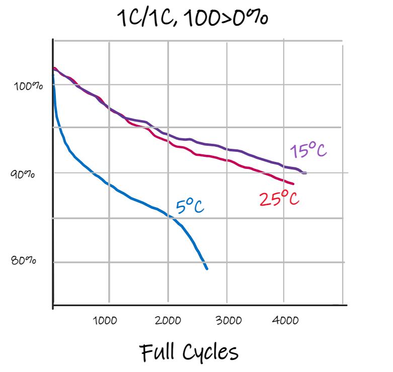
However, particularly NMC cells on the other hand suffer heavily from being charged at low temperatures (<5-15°C), especially at high C-rates3 – which of course is a conflicting requirement! For more information see the figure and the inlay.
Li-Ion batteries can be regarded safe. “Self ignition” can, if at all, only be assumed if internal microscopic defects accumulated to critical levels. In simple terms Li-ions travel from one pole to another inside a cell, while electrons take that journey through the electric circuit of the vehicle. Under normal conditions, the ions migrate into the opposite electrode to be reunited with the well-travelled electrons. Yet if it is cold, the current is high (fast-charging) and/or that host electrode is already well-filled, this migration becomes as cumbersome as boarding an already packed plane with another three dozen shivering passengers. So, under such conditions, it is electrochemically often more favourable to form metal deposits on the electrode – “Lithium Plating”, the “bad form” of residue.
A continuous repetition of this process stacks up such defects, potentially up to the point of penetrating filaments that cause internal short circuits (“dendrites”). Those in turn may generate heat, which is vital for speeding up chemical processes, leading to even more heat and gases being generated – a self-sustaining process called “Thermal Runaway”. Such a situation becomes ballistic in less than 5 minutes, eventually violently venting gases in the form of electrolyte-soaked, thick white vapour clouds.
Note: the conditions that facilitate plating are only partially controllable by a vehicle’s battery management system. It is the operator’s responsibility to monitor and foster their batteries, just like careful storage, handling and sensible monitoring of flammable liquids is unquestioned best-practice.
SOC comes into play…
So while C-rate (current) and temperature typically form a complex interplay, and susceptibility to temperature often heavily differs from calendric to cyclic aging, the real surprises are brought to us by: the SOC!
The SOC can have a significant impact on battery lifetime, both the idle SOC during parking (calendric aging) and the SOC window or range in which an asset is operated (cyclic aging). While again only one of hundreds of examples, it is quite telling which potentials lie hidden in that factor: in the following figure, the degradation evolution of two almost identical usecases of a hi-quality NMC cell is shown. Both use only c. 50% of the battery (not uncommon), and the first (green) does so in the upper half (100>50>100>…%, i.e. returning half full to the depot), while the second one (purple) has a daring driver: starting at 50% and returning virtually empty (50>0%). The impact on degradation is incredible: the second battery will live 2-3 times longer than the first one, reducing total cost of ownership by more than 50%.
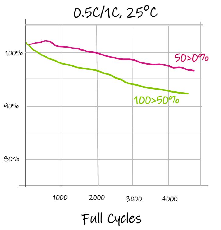
Who dares wins! Really? When it comes to these susceptibilities, generalisations are very dangerous. There might be ample amounts of cells that react completely differently – one often quoted rule of thumb is that by avoiding high (>90%) and low (<10%) SOC regions, lifetime can be greatly extended. However not in this example – it’s not depicted, but an operation “in the middle” (75>25>75>…%) even exhibits a slightly faster degradation than the blue one!
Focus on the battery stress level
That sounds complex, confusing and almost unmanageable. And yes, not even a trained expert can assess how stressful a given usage profile is even by analysing it manually, i.e. by assessing C-rate profile, temperature evolution and SOC ranges and comparing them to the multi-dimensional susceptibility matrix of the cell type5.
To reduce complexity there is the concept of the stress level, a simple number that tells the observer whether a given usecase is more or less stressful than a nominal reference case (such as the default design and warranty conditions like “End of life after 8 years”) – a stress level of 1.0 means that a given case is circa as stressful as planned, and a stress level of 2.0 means that the battery under the given influencing factors is probably degrading c. two times as fast as planned.
There are tools to automatically analyse the stress level in a monitoring platform, which can be very handy not only to asses risks and potentials, but also to adapt usecases accordingly.
The role of the BMS
There is a discussion ongoing – for years now – of whether or not it’s the battery electronics’ (BMS’) task to control the influencing factors and keep them under control. Yes, it is. It will prevent detrimental usage that might cause imminent threats for safety (“very high stress”). But except for very rate instances, it is neither designed nor intended to make recommendations for the ‘most optimal’ stress level.
In other words: I will prevent you from slurping 2 bottles of red wine, but it will not recommend drinking 1 cup of ginger tea instead.
Outlook
Interestingly, the global trend is towards ever higher energy densities (longer range), which is often dearly paid for by sacrificing lifetime. Yes, average stability is going down! This is particularly true for passenger car automotive cells, but might, sooner or later, also affect heavy duty vehicles. In any case, the severe and profound susceptibility of all Li ion cell types to the influencing factors should alert us all and raise the awareness for the huge optimization potentials that might lie dormant in so many use cases.
Take home messages
We have not even touched other chemistries like LFP or LTO, and also the striking impact that adapting of charging profiles (e.g. by adapting parking/idling SOC) can have on calendric aging was omitted for the sake of brevity. But still, some take home messages can be derived:
- Each subtype of Li ion cells has their unique and often complex susceptibility to external influencing factors – and calendric aging (parking) must be distinguished from cyclic aging (operation)
- Both result in different forms of Li ions becoming inactive – always leading to a more or less pronounced fade of capacity (and increase of resistance), and sometimes even leading to dangerous residue building up (Li Plating)
- Different usage conditions thus lead to different stress levels (or degradation evolutions), and just counting cycles or age can never result in an adequate assessment of degradation!
- In other words: one must still check the capacity and SOH regularly and independently
- This also dictates an elevated awareness for both dangers (potential induction of safety issues, see inlay and following articles) and potentials of the impact of different influencing factors on the rate of degradation – e.g. by monitoring the battery stress level
- And last but not least: slight adaptions to usage profiles can reduce battery stress significantly and help to extend asset lifetime by 10 to 50%, and in some extreme cases even by the factor of 2 or more!
Footnotes:
1 Often referred to as „solid-electrolyte interface“ (SEI), as this residue forms an interface between the solid electrodes and the electrolyte.
2 The cell temperature is of course never entirely independent of the ambient temperature. Especially in battery systems without temperature control (no active heating/cooling), cell temperature is directly influenced by the ambient. And even if a system is actively controlled, the cell temperature will approach ambient temperature after prolonged off periods.
3 „C rate“ is the normalized current; instead of speaking of 20A – which can be a lot for a small (e.g. 2Ah cell), but negligible for a large 1000 Ah battery – one often divides the current by the nominal capacity: 10C in the first case, 0.02C in the latter. 1C thus means: empty in c. 1h.
4 Artistic reproduction; Charging and discharging @1C, full SOC window (0 – 100% – 0%), temperature varied
5 This susceptibility matrix is often called stress map. And it is most often even unknown, at least in parts, to both cell and system manufacturer because of the sheer extend and complexity. And as it allows for the said great optimization potentials, it is also often a well-kept secret.
Originally published on Sustainable Bus

